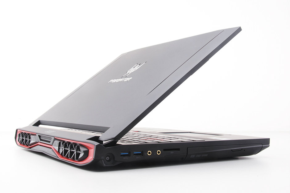
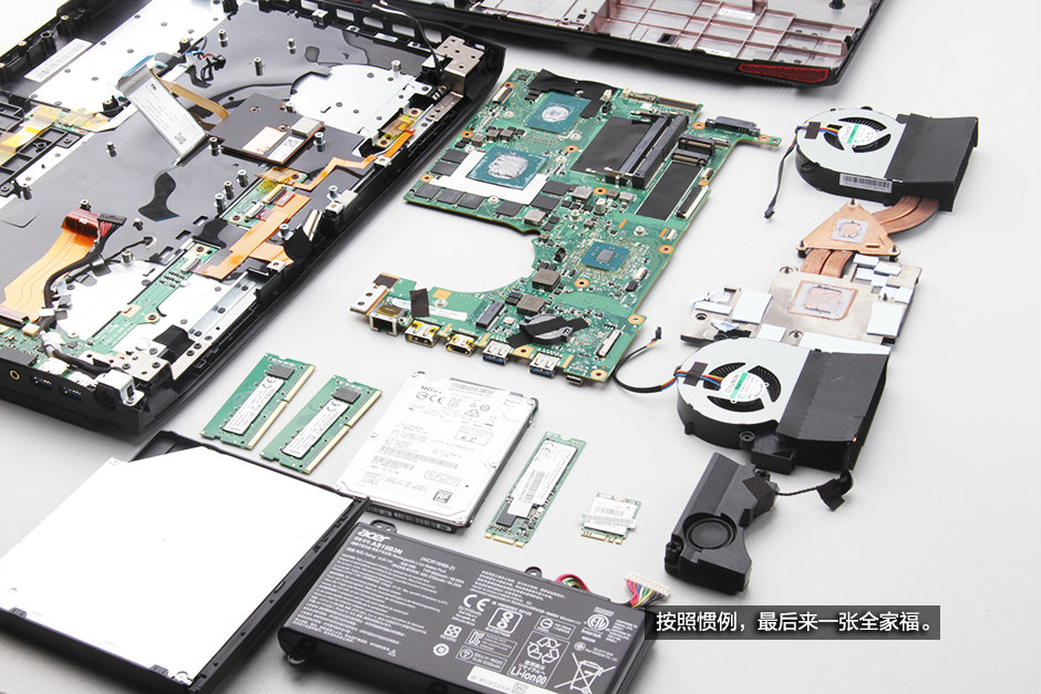
In this guide I’ll disassemble an Acer Predator 15 G9-591, I will remove the bottom cover, optical drive, hard drive, SSD, RAM, wireless card, cooling fan, heat sink, and motherboard.
Looking for more guides from laptopmain.com? Follow us on Facebook for all the latest teardown news.
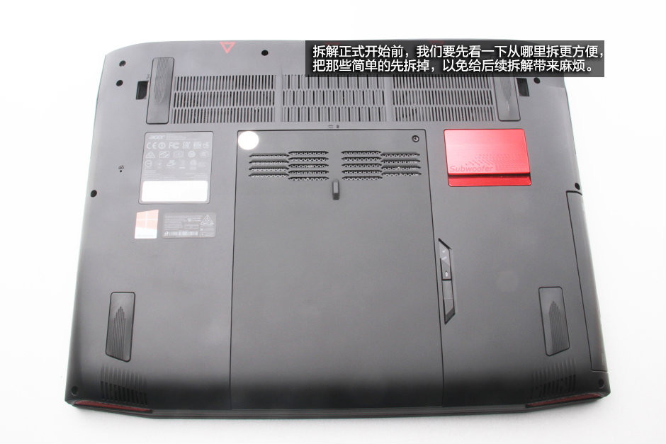
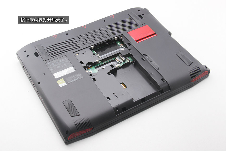
1. Removing the optical drive
Turn over the laptop. We can see from the picture. The laptop has a service cover and an optical drive.
There is no screw securing the optical drive.
Slide the latch by the arrow. At the same time, pull the optical drive to the right.
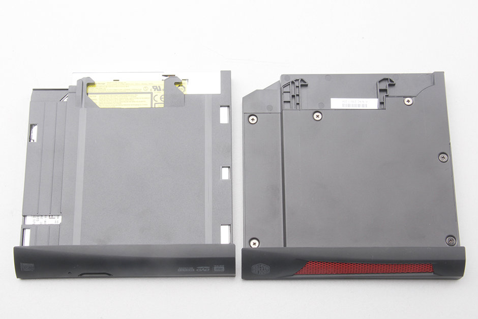
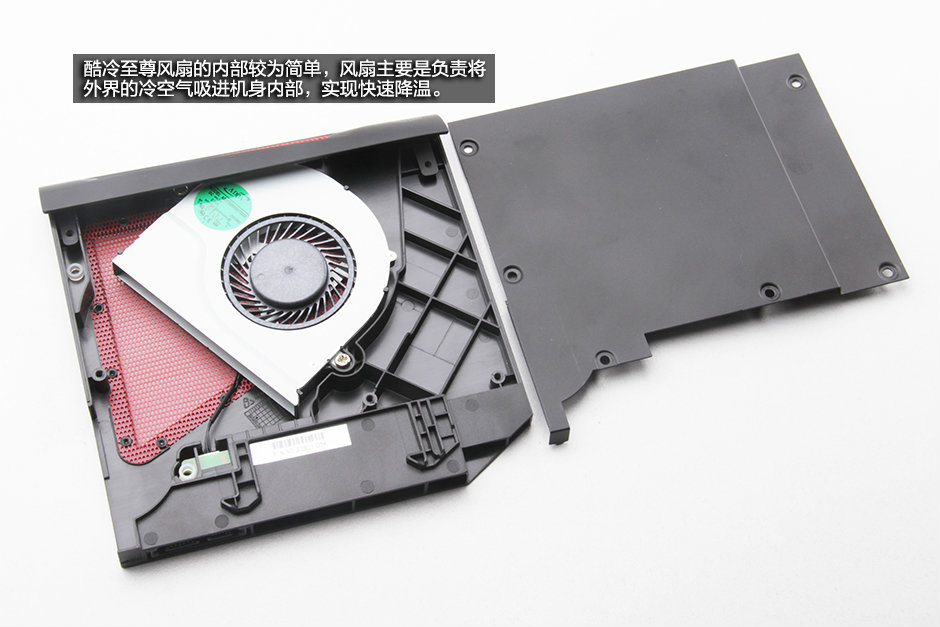
The left is an optical drive, and the right is the cooling fan module (comes with the laptop).

If you do not need an optical drive, you can remove the optical drive, install the fan to the location of the optical drive.
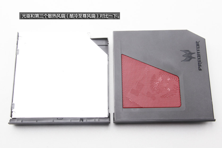
Remove six screws. You can open the cooling fan module.
2. Removing the service cover
Remove two screws securing the service cover. Pry up and remove it.
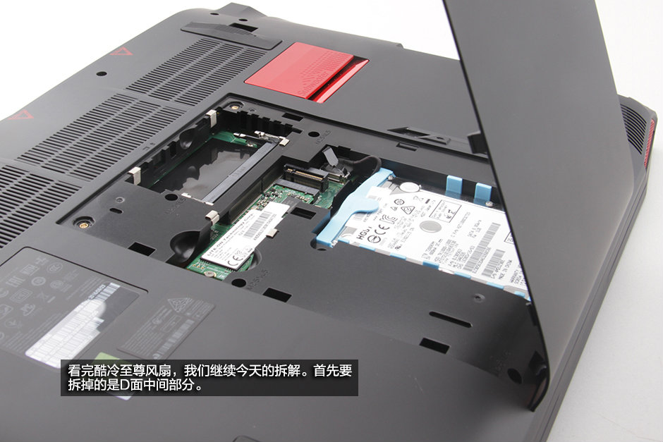
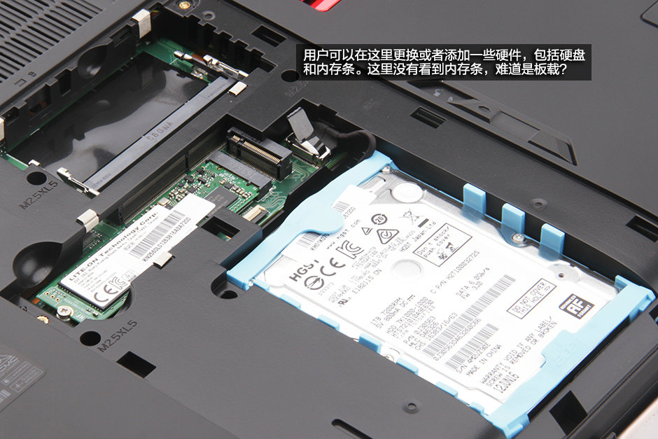
Under the service cover, we can see a hard drive, an SSD, a spare M.2 slot and two spare RAM slots.
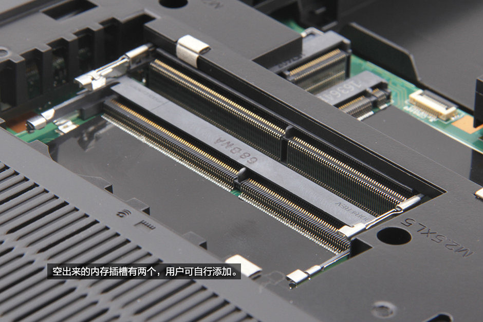
3. Upgrade the RAM
Here’re two spare RAM slots. The user can add RAM easily.
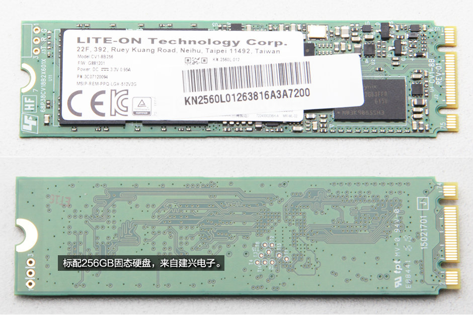
4. Removing the SSD
Remove one screw and take out the SSD of its slot.
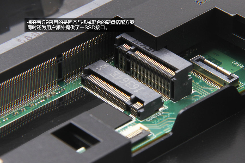
The Acer Predator 15 G9-591 comes with a LITE-ON 256GB M.2 SSD.
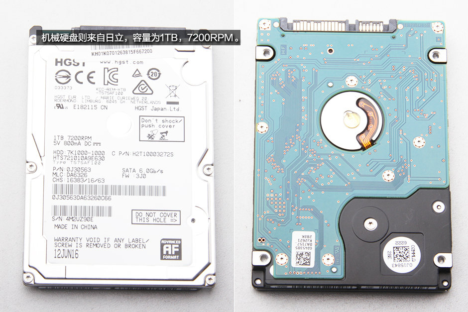
5. Removing the hard drive
Disconnect the SATA cable from the motherboard. You can remove the hard drive module.
HGST 1TB 7200RPM hard drive
5. Removing the bottom cover
Remove all screws securing the bottom cover. Pry up and remove it.
Do not forget to remove the screws under the service cover.
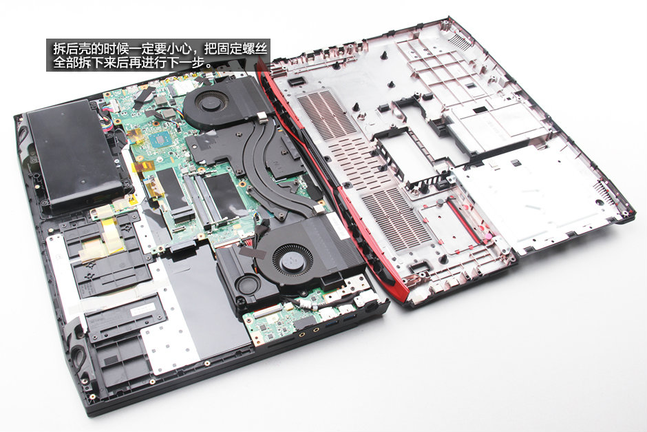
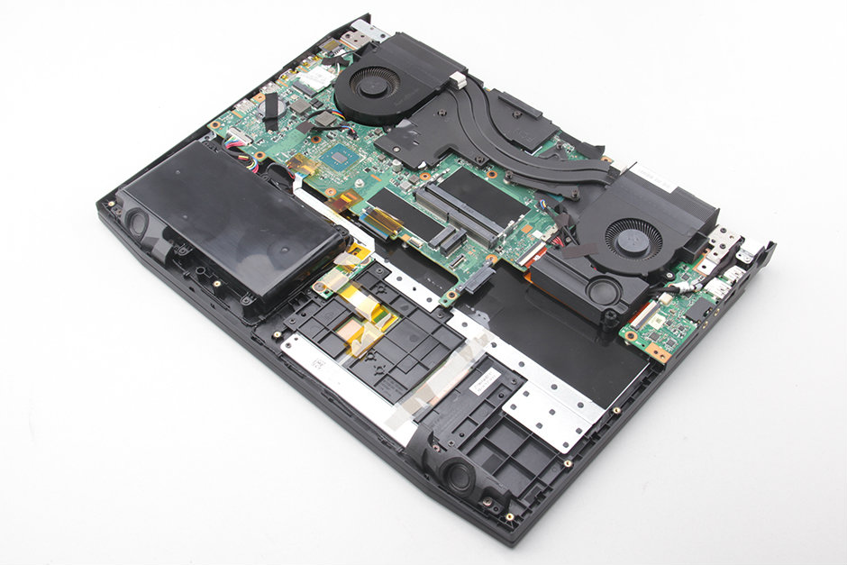
Under the bottom cover you can get access to the following internal components:
– Battery
– Heat sink and Cooling Fan
– Wireless card
– Speaker
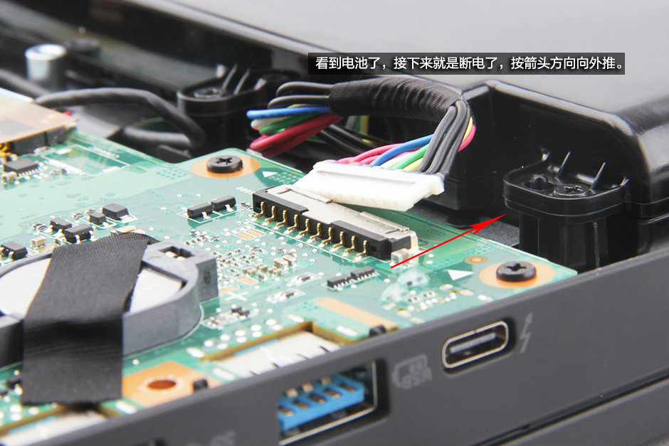
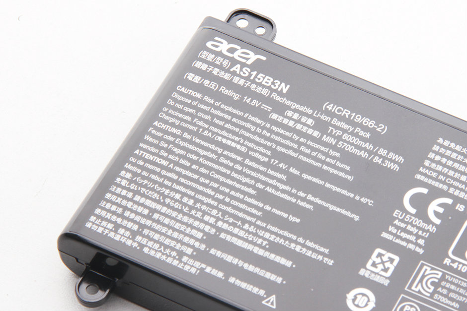
6. Removing the battery
Remove all screws securing the battery.

Disconnect the battery connector from the motherboard.
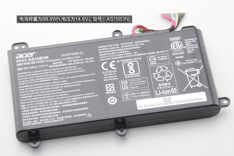
The Acer Predator 15 G9-591 comes with a 14.8V, 88.8Wh Li-ion battery, Acer P/N: AS15B3N.
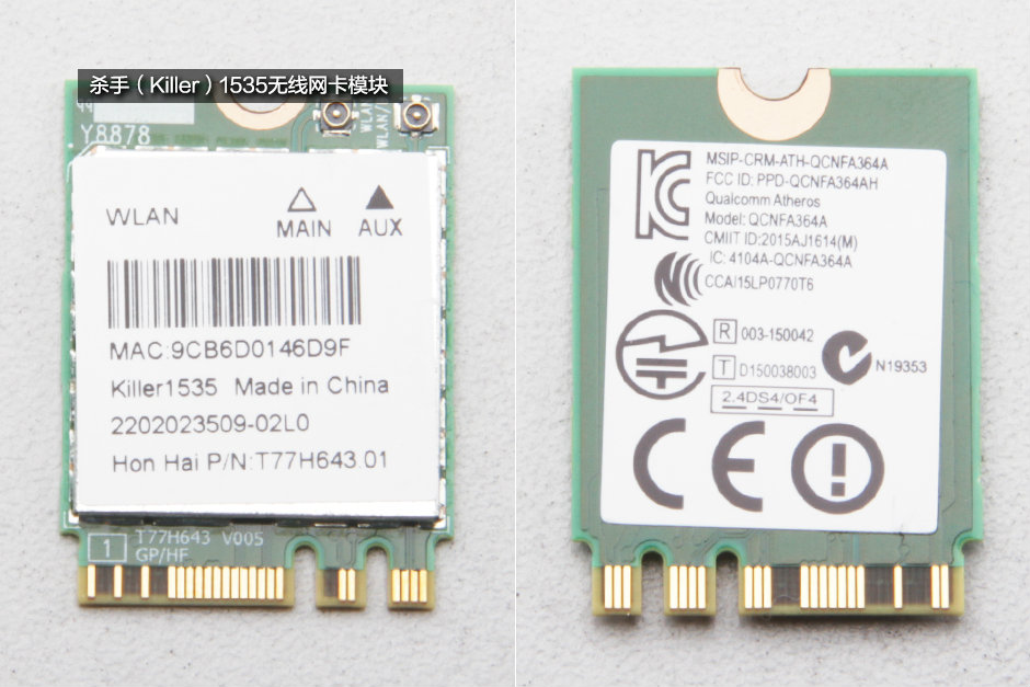
6. Removing the wireless card
Unplug two antenna cables and remove one screw. You can remove the wireless card.
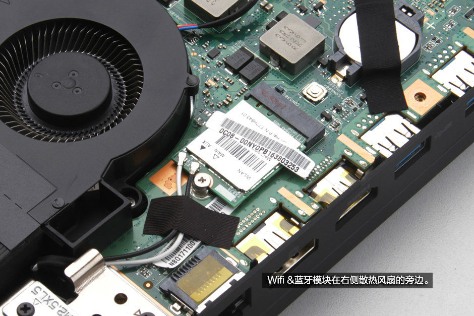
Killer 1535 wireless card, Hon Hai P/N: T77H643 01
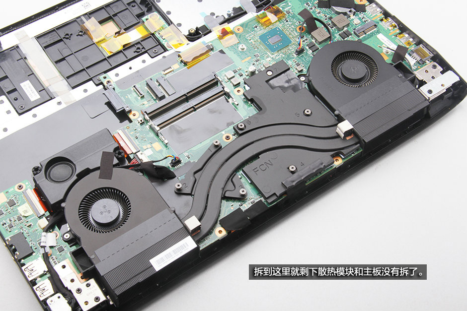
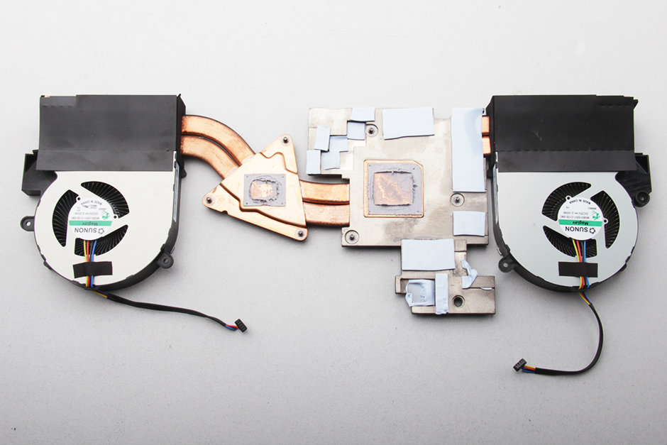
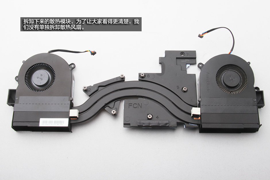
6. Removing the heat sink and cooling fan
Disconnect two cooling fan cables from the motherboard.
Loosen all screws securing the heat sink and cooling fan.
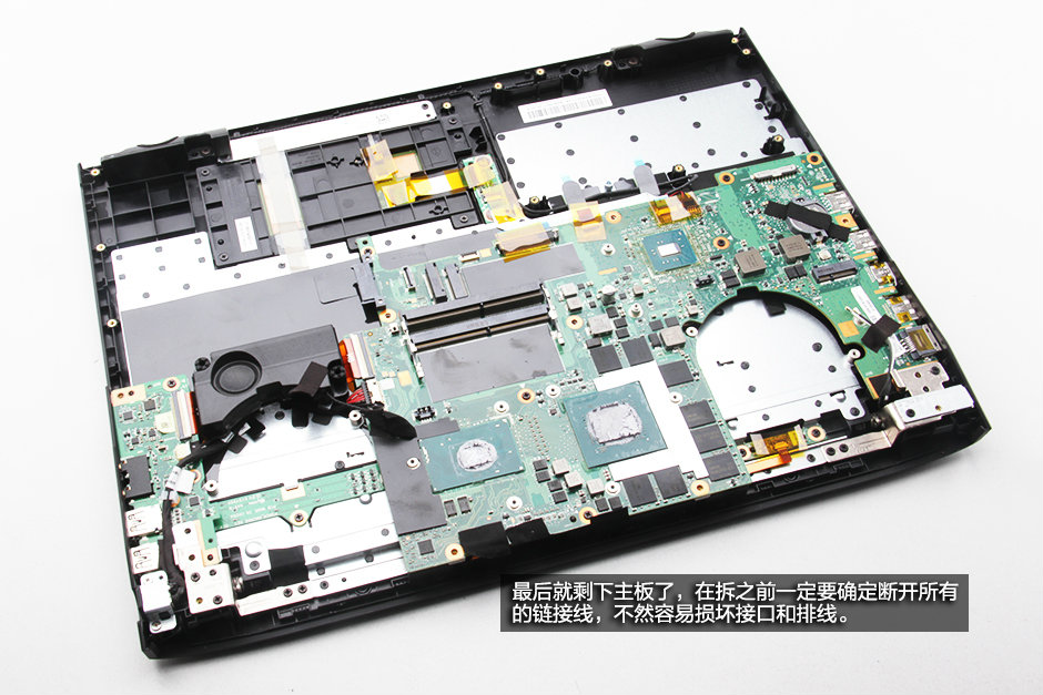
7. Removing the motherboard
Disconnect all cables from the motherboard.
Remove all screws securing the motherboard. And then take out the motherboard.
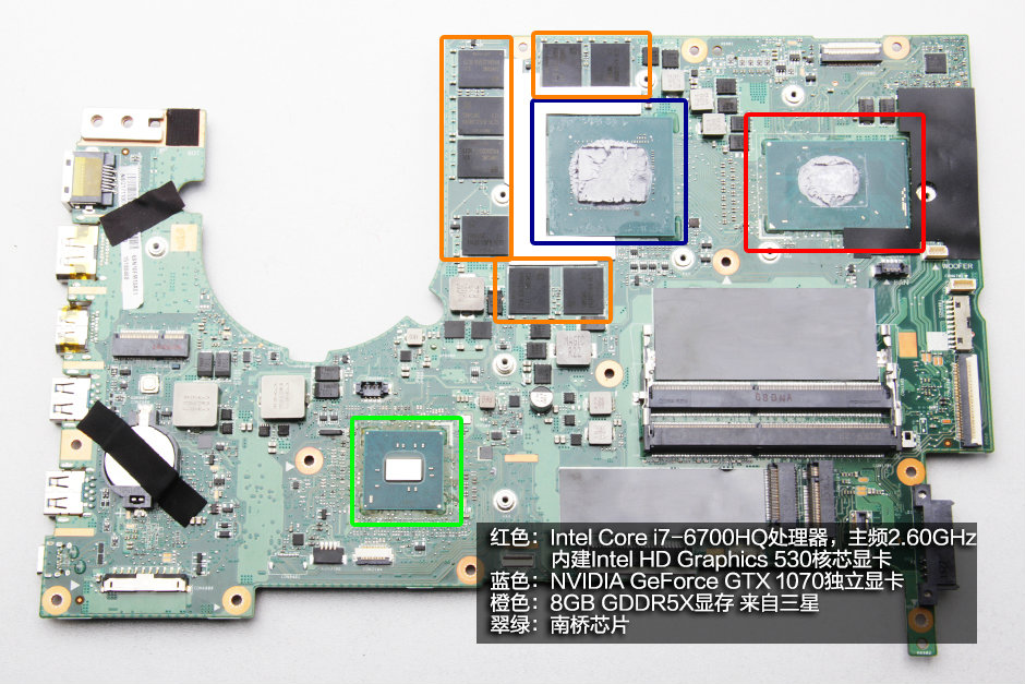
Red: Intel® Core™ i7-6700HQ 2.60 GHz Processor (6M Cache, up to 3.50 GHz), built-in Intel® HD Graphics 530
Blue: NVIDIA GeForce GTX 1070 graphics card
Orange: Samsung 8GB GDDR5X video memory
Jade Green: South Bridge
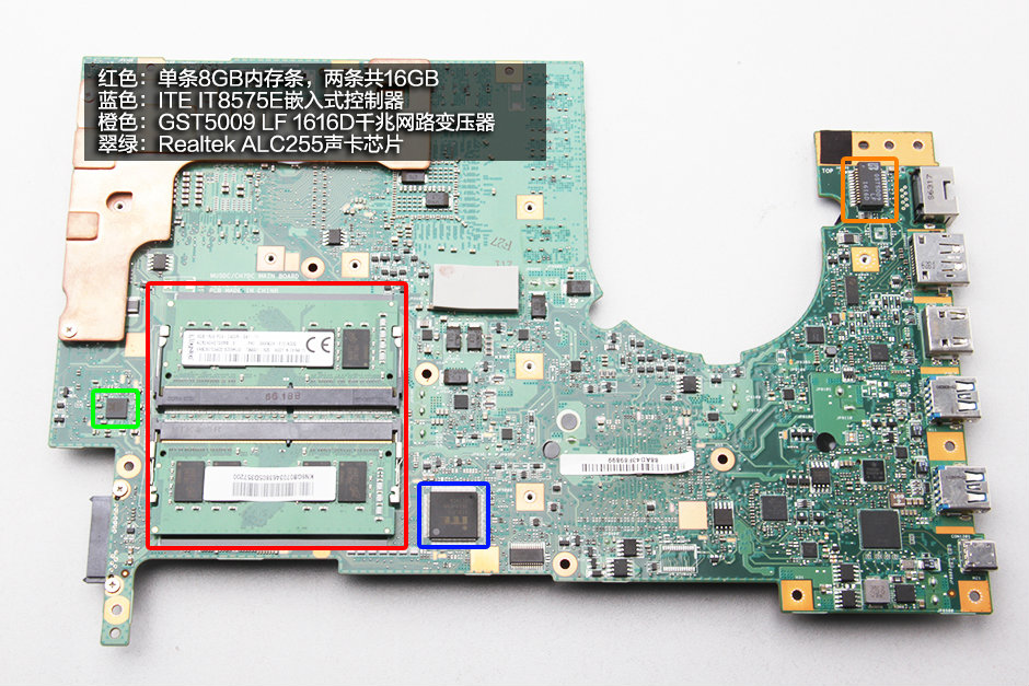
Red: Two 8GB DDR4-2400MHz RAM
Blue: ITE IT8575E embedded controller
Orange: GST5009LF 1616D Gigabit network transformer
Orange: Realtek ALC255 sound card
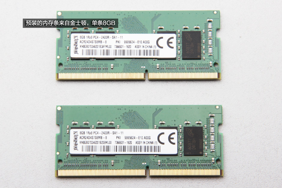
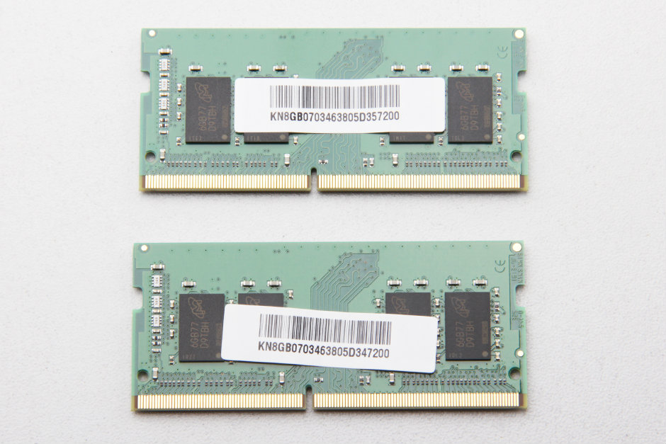
Two Kingston 8GB DDR4-2400MHz RAMs
Source: pconline


")


