The dual-SIM (Nano) Honor 7X runs Android 7.0 Nougat-based EMUI 5.1. It is powered by an octa-core HiSilicon Kirin 659 SoC (4 x Cortex-A53 cores clocked at 2.36GHz + 4 x Cortex-A53 cores clocked at 1.7GHz) coupled with 4GB of RAM and houses a 3340mAh battery. The phone features a duo of 16-megapixel and 2-megapixel rear cameras and an 8-megapixel front-facing camera.
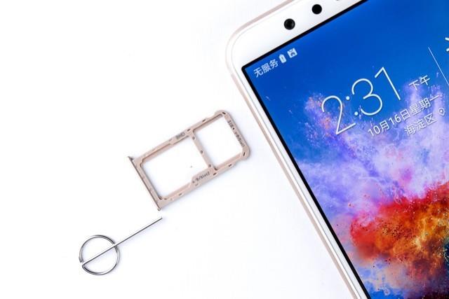
The Honor 7X comes in three storage variants: 32GB, 64GB, and 128GB. The phone support expandable storage via microSD card (up to 256GB) in a hybrid dual-SIM configuration.
For the freshest produce, find us on Facebook for the latest teardown news.
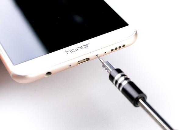
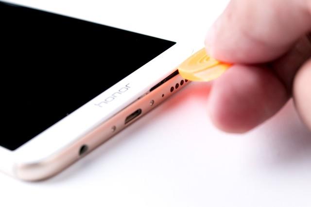
First of all, remove the SIM card tray.
Remove two screws beside the Micro USB port.
Insert a pick under the display assembly and slide the pick to separate the back cover from the phone.
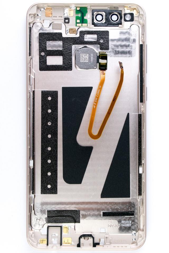
Be careful, you can not separate the back cover completely, because the fingerprint module cable still connecting to the motherboard.

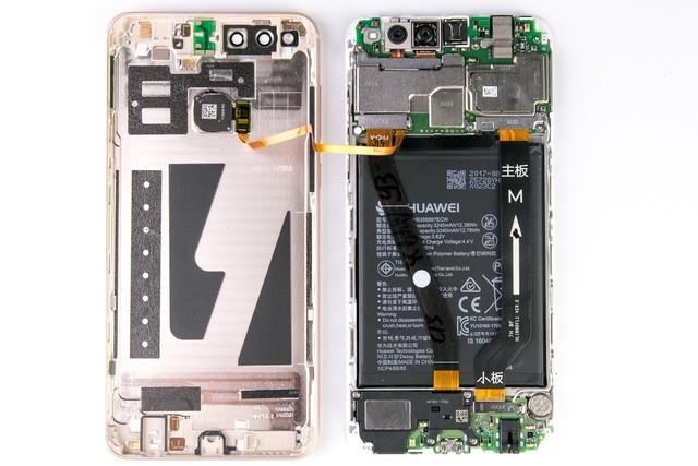
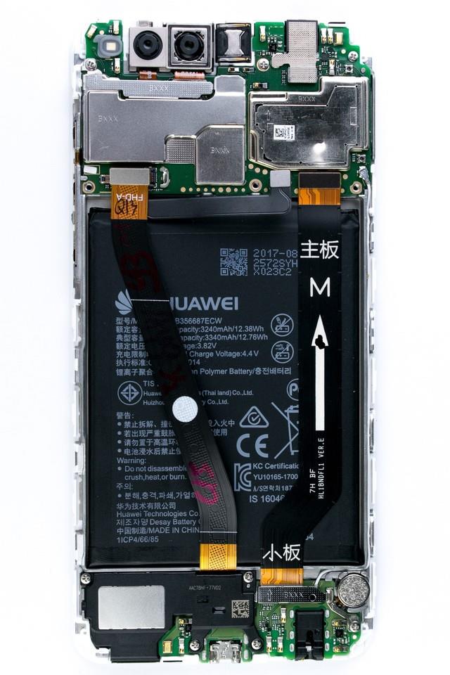
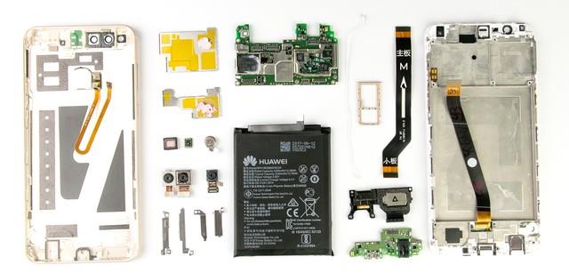
Opened the back cover, the internal structure of the Honor 7X gave me the first feeling is no feeling. Because there are too many Android phones are with three-stage structure. But this does not mean that the dismantling of this no surprise. There are sealing, thermal design, motherboard chip density and other considerations of the internal design of good and bad details waiting for us to explore.
We need to disconnect the battery connector, remove the metal plate and disconnect the battery connector.
The four corners of the back cover are with the injection thickened, which brings a good the anti-bump ability, combined with plastic wrap screen module outside, also can reduce the impact force by the glass in the body when falling, reducing the risk of the broken screen. The antenna contact surface on the top and bottom of the back cover with the gold-plated coating, with strong corrosion resistance; around the fuselage has sealed foam. In general, this design is at an excellent level in anti-aging and tightness at the same level of mobile phones.
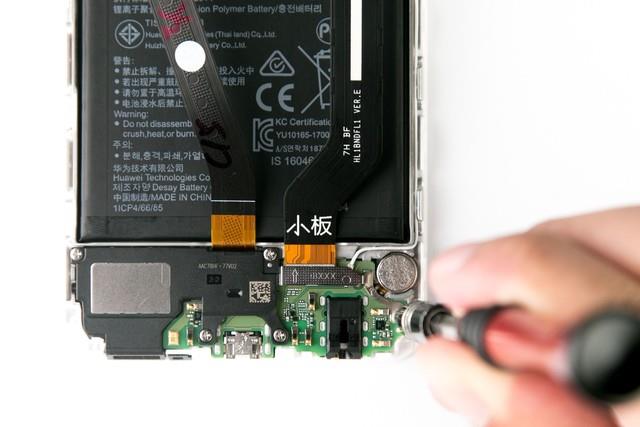
The whole body three sections are: motherboard and camera area; battery module; sub-board vibrator component area. The connector on the motherboard in addition to the front camera using conductive adhesive tape fixed. The rest of all connectors is fixed with the metal cover, so as to greatly avoid the strong vibration caused by the connector off the connector base. It is worth mentioning that the handset in order to give a full screen vacated place with a vertical design, it is connected via the small board on the back cover to the motherboard, is a good design scheme.
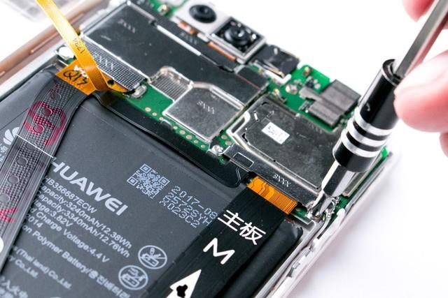
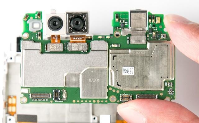
Remove all screws securing the motherboard and pull out the motherboard.
The chips on the front of the motherboard are covered by the metal shield to prevent the electromagnetic signal from interfering with the chip.
I found that compared to other phones, the phone less touch cable, should be integrated with the LCD cable together, and the button is connected to the motherboard by metal contacts.
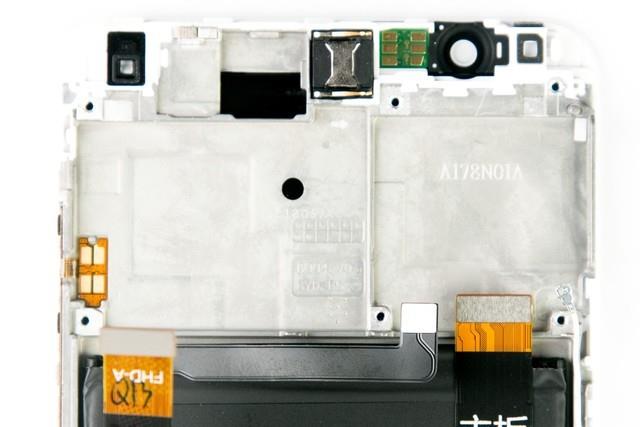
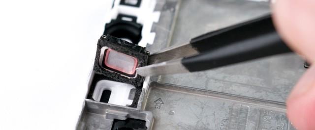
The handset is firmly fixed in the body, and a circle of seal ring foam on the handset to prevent from dust, water vapor into the phone body.
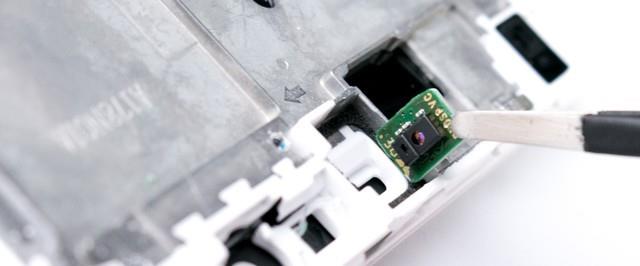
The light distance sensor uses an independent module to connect with the main board through the contact, and if it fails, it can be replaced separately.
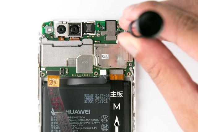
Disconnect two connectors for the main camera.
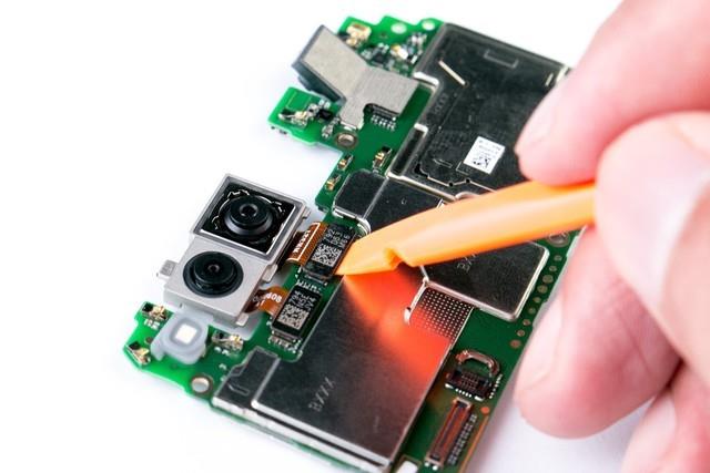
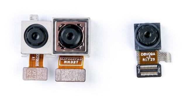
You can see the thickness difference between the main camera and the secondary camera is still very large.

The 16MP main camera support PDAF, as for the aperture and photosensitive element sizes or model, at present I have not found; vice camera only 2MP, its significance is mainly to help the main camera to achieve portraits Mode, itself is not involved in imaging, so the parameters are not so important.
Separate the metal shield. You can see the largest piece of a chip coated with heat grease.
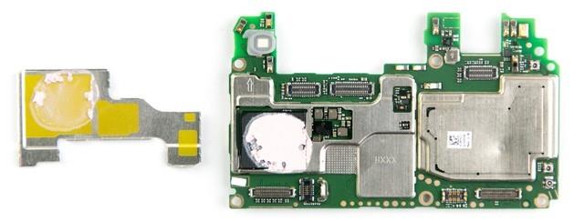
Clean the grease. You can see this is a memory chip from Samsung. The next side of the shield opened, you can see the RF amplifier chip.

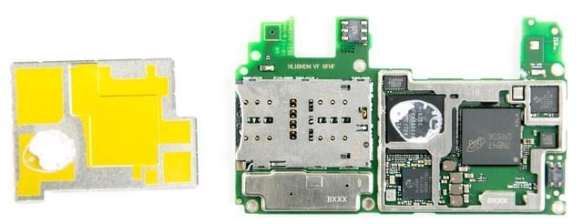
The card slot accounted for most of the space. The other shield is hidden more chips, including Micron flash, power management chip, Wi-Fi, and RF chip, etc.
Remove five screws securing the loudspeaker and the sub-board.
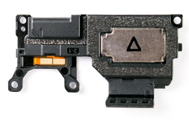
Then take off the speaker module, from the lettering above to see that this speaker comes from AAC.
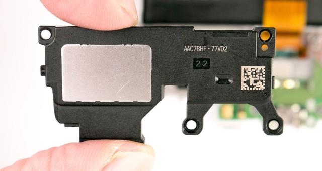
A circle of foam on the back of the speaker is designed to seal the bottom of the fuselage, which is connected to the sub-board with metal contacts.
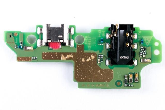
Take off the sub-board. You can see the vibrator module is connected to the sub-board through the metal contacts.

The rear part of the sub-board is designed with capacitive elements. It can be seen that both the data interface and the audio interface are soldered to the sub-board.
Tilt the edge of the battery, and then insert the card under the battery, until the battery can be an easy removed (this step requires a certain skill, avoid excessive deformation may damage the battery).
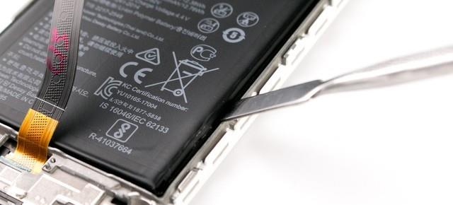
It comes with a 3340mAh, 12.76Wh.


We give the Honor 7X dismantling the difficulty rating is easy. The total number of screws only 13, the only difficulty is the battery uses a large area of strong double-sided adhesive, if you want to replace the battery may have to spend some time.

")
")


Hi, great information man,keep up the awesome work.
I am loving this phone. Also, may I know if I can use the speaker grille as a ‘Lanyard eyelet’? to fasten a lanyard cable through it? Is the gap enough for a 1mm wire? Do you think the dimensions of the speaker grille allow it?
I do not recommend use the speaker grille as a ‘Lanyard eyelet’, if necessary, you can buy a case with lanyard.
Hi,
I want honor 7x mother board,
Please search it on eBay on aliexpress.
Is there a way to remove the Sim card reader from the motherboard.
I don’t think so, it should be soldered to the motherboard.
What about desoldering the existing one and soldering on a new one.
I did a screen replacement following the instructions. However, after powering out there was light on the lcd but it didnt come up (i tried the original screen but the same thing) any suggestion how to fix this.
Do you know what screwdriver I can use to take the case off the honor 7x? I know they are tinier than anything I have.
Hello i have a Honor 7x but the battery died and i want to replace it but i can’t find what type of screwdriver is needed to disassemble the phone, can you help me?